

Optical Transceiver Q&A
A place to compile all the Q&A-format posts on transceivers for anyone who's interested.

Ideally, this document will grow - slowly but surely - into a comprehensive and powerful reference for anyone working with optical transceivers or optical network design. And it won’t be a solo effort!
I’m maintaining a copy of this on LinkedIn too for anyone to contribute and add to. With citations of course, as every contributor should also be available as a follow up for further questions from any reader.
This means no anonymous contributions - Everyone who adds, including me, will always be accountable for the correctness of the information shared.
Though I suspect it will just be me for a long time!
Questions + Answers we have so far:
How do I choose between using OSFP and QSFP-DD for 400G?
Can I use different ranges (like SR/DR/FR etc.) of transceivers with each other?
I want to breakout an 800G into 2 x 200G, can I do this?
Should I buy more 800G ports now, or wait for 1.6T ports?
What’s the difference between MPO-16 and MPO-12?
1 - How do I choose between using OSFP and QSFP-DD for 400G?
https://www.linkedin.com/posts/hitesh-kumar58_qsfp-osfps-networks-activity-7331253259682131968-lrQo

So I believe the two main reasons are:
Backwards compatibility with QSFP56
Thermal management
Backwards compatibility:
QSFP-DD ports can accept QSFP56 and QSFP112 transceivers too if needed - but note that this wont work the other way, for a 400G QSFP112 port to take a 400G QSFP-DD transceiver etc.
You cant put any other transceiver form factor into an OSFP port however without special adapters, but you could always use breakout cables if you needed to use an OSFP switch with QSFP NICs, with the bandwidth splitting too.
And I suppose with OSFP you’re better set for upgrades towards 1.6T and beyond, with upcoming 16-lane OSFP-XD modules which will be backwards compatible with current OSFP form factors (both flat top and finned I presume)
Thermal management:
OSFPs are physically larger and can come with flat top or finned top form factors.
This is partly due to having more space as they were designed around 8 lanes from the start, whereas QSFP-DD are designed to fit 8 lanes in a sort of 4 lane compatible form factor.
This means that with QSFP-DD, the switch itself must have heatsinks built into the ports to help keep the module cool, but with OSFP, the modules have heatsinks built into them.
Further, for OSFPs, they come in slightly shorter flat top form factors which are intended for low port density appliances like servers, as well as finned top form factors for high port density switches.
Follow up links:
Blog by ProLabs: https://www.prolabs.com/400g-which-form-factor
Article by QSFPTEK: https://store.qsfptek.com/blogs/article/qsfp-dd-wiki-and-comparison-of-qsfp-dd-vs-osfp-and-qsfp
Arista Networks‘ very detailed documentation on this: https://www.arista.com/assets/data/pdf/Datasheets/Arista-400G_Optics_FAQ.pdf
The ENTIRE specifications for QSFP-DD and OSFP if you want to use NotebookLM or something (please don’t try to read it all): http://www.qsfp-dd.com/wp-content/uploads/2017/03/QSFP-DDrev2-0-Final.pdf and https://osfpmsa.org/assets/pdf/OSFP_Module_Specification_Rev5_21.pdf
2 - Can I use different ranges (like SR/DR/FR etc.) of transceivers with each other?

Maybe. It’s not something I’ve experimented with at all, and sources seem mixed.
Generally it’s best not to mix up transceivers with specified ranges.
The compatibility isn’t just some arbitrary value determined by matching names, it depends on a lot of factors:
Wavelength
Data rate
Modulation
Fibre cable type
and a few more things.
Range is determined by the above, and so it’s not that different are incompatible by design, but that other factors might make them un-interoperable.
1️⃣ VSR <-> SR:For example:
VR or VSR (Very Short Range) is designed for <100m- and SR (Short Range) is for up to <300mBut both run at 850nm, using MMF fibres.
The issue might arise with cables though, as SR transceivers could be made for MPO-12 or MPO-16 cables. But I have never seen a VR using MPO-16.
2️⃣ DR <-> FR:
Similarly, FR and LR might work since both use O-band (1260nm-1360nm) and use LC duplex cables. But then you have to make sure the modulation is the same as:
Lower bandwidth connections will use NRZ
A higher bandwidth might use PAM4
It seems even this information isn’t universally agreed upon, as sources seem to vary a little between the exact distances that these categories cover.
The values above were taken from Asterfusion Data Technologies‘ blog post here: https://cloudswit.ch/blogs/choose-400g-optical-modules-for-data-center/
Some sources say that actually you can mix some types with the shorter type being the one that determines the resultant maximum range of the connection. A very detailed guide from Arista Networks here: https://www.arista.com/assets/data/pdf/Datasheets/Arista-400G_Optics_FAQ.pdf
For example, it may be possible to interoperate a FR with an LR, limited to 2km (by the FR). The catch is that LR modules transmit at a higher minimum power than maximum power that FR can receive, and so a minimum amount of attenuation (or signal power loss) may be needed to make this work.
I think the best thing to do is still to consult with the vendor and get them to help you with testing if this is really an issue to you. Though I can’t imagine that this would be a common occurrence.
Follow up links:
A post from Cisco Patrick Chou on using 400G DRs with 100G FRs: https://blogs.cisco.com/sp/heres-an-easier-way-to-upgrade-to-400g-optics
A great blog post by Asterfusion Data Technologies on various ranges of 400G optics: https://cloudswit.ch/blogs/choose-400g-optical-modules-for-data-center/
FAQ document from Arista Networks on 400G transceivers: https://www.arista.com/assets/data/pdf/Datasheets/Arista-400G_Optics_FAQ.pdf
A really comprehensive interoperability matrix tool from Cisco - not easy to use but might be useful for non-cisco products too:
https://tmgmatrix.cisco.com
3 - I want to breakout an 800G into 2 x 200G, can I do this?

It depends on if the hardware can be split up properly to accommodate.
Generally, you’d get the right transceiver for the right port and divide the bandwidth from the source equally, but sometimes that’s just not possible.
For example, you might be in a (not so uncommon) situation like:
Having existing infrastructure using 800G OSFP switches
Needing an additional small setup with a few smaller endpoints
Additional endpoints having 200G or 400G QSFP NICs
In a case like this, you might be unsure about which QSFP type you’d use and how you’d breakout from an 800G OSFP.
But it is possible, and also fairly simple: Stop thinking about transceivers and start thinking about lanes!
The 800G OSFP has 8 x 100G (O= Octal) lanes, using PAM4 modulation. In contrast, a 200G QSFP56 would be running 4 lanes (Q = Quad) at 50G using NRZ modulation. Splitting an 8 lane OSFP using a 4 way breakout would mean each endpoint gets exactly 2 lanes of 100G.
You need a transceiver that can handle 2 x 100G lanes!
So the answer is that you’d use 400G transceivers anyway, since QSFP112 400G transceivers have 4 x 100G lanes.
Both the source and destination will be using the same lane rate and modulation. The destination 400G would be running with only 2 of their 4 100G lanes. Half of the lanes will be inactive and the transceiver will use less power.
In summary:
Use a dual-port OSFP 800G at the switch
Use 2 breakout cables that split into 2 ends each
Use 400G QSFP112 transceivers at the endpoints
I don’t know if its possible for transceivers to automatically shift down to a lower lane rate with a different modulation using their gearboxes. It sounds like it can be done, but I cant find any sources on this - perhaps another post!
If needed, it’s even possible to split down to 8 x 100G ports! But going any further becomes difficult/impossible. After all an OSFP transceiver will only have 8 channels to distribute in breakouts. Any more needs another switch.
UPDATE:
Wait - 2 x 100G transceivers exist!
Previously, I said that 400G transceivers (and 400G NICs) are used for breaking out 800G ports into 200G ports - This is still true.
But now I learn that you can also use 200G transceivers and NICs!
I thought that 200G QSFP transceivers would (since “Q” = Quad) use 4 lanes at 50G for the optical interface. This means that they are incompatible with 800G OSFP or 400G QSFP transceivers that run at 100G per lane.
But it looks like the “Q” doesn’t necessarily define both the optical AND electrical interface! There exist QSFP56’s that present 4 x 50G electrical lanes but 2 x 100G optical lanes.
These are designed for 200G QSFP NICs it seems, compatible with the electrical interface of the port but lets you split from an 800G (8 x 100G) source. I became aware of this just recently with FIBERSTAMPs post on this: https://lnkd.in/ehRZ6_WE (thanks to Anders Zhang/Chang).
I would imagine there are other vendors too but I’m finding it difficult to find sources - not entirely clear. This QSFP-DD (8 x 25G NRZ) from FLEXOPTIX GmbH appears to present 2 x 100G optically but it seems to be a dual 100G port instead of a single 200G port: https://lnkd.in/eN9vkpRSStill
Still looking for other sources.
Comments:
“...the answer lies in the DSP being used inside the module. Take our 400G QSFP-DD PLR4 transceiver for example, utilising PAM4 technology, this module can convert 8-channel 53.125 Gbit/s electrical data to 4 parallel channels of optical signals, each supporting106.25 Gbit/s data transmission. Reversely, it can convert 4-channel 106.25 Gbit/s optical signals to 8-channel electrical output data on the receiver side. The diagram below illustrates how it works.

“...the step that takes 8 × 50 Gb/s electrical lanes (400 GAUI-8) and outputs 4 × 100 Gb/s optical lanes inside a 400 GbE pluggable is the lane aggregation in the module’s DSP/gearbox.
(GAUI = Gigabit Attachment Unit Interface - the short-reach, board-level electrical link between the host ASIC and the module. 400 GAUI-8 means eight 53 GBd PAM4 lanes. I found what looks like a concise primer in the “Standards” section of this blog post: https://blog.fluxlight.com/2022/12/13/deep-dive-400gbase-lr4-qsfp-dd-optical-transceiver/)
In a duplex part (e.g., QSFP-DD FR4) that DSP/gearbox output then feeds a CWDM mux/demux so the four 100 Gb/s optical carriers share one fiber pair.
I found two example datasheets that appears to spell this out:
1.) T1-Nexus QSFP-DD-400G-DR4: “converts 8 channels of 50 Gb/s (PAM4) electrical input data to 4 channels of parallel optical signals, each 100 Gb/s.”: https://t1nexus.com/product/t1-qsfp-dd-400g-dr4/
2.) EdgeOptic 400G-QSFP-DD-2.1 (FR4): “converts 8 channels of 50 Gb/s (PAM4) electrical input data to 4 channels of CWDM optical signals and multiplexes them into a single channel for 400 Gb/s optical transmission.”: https://edgeoptic.com/products/400g-qsfp-dd/400g-qsfp-dd-2-1/“
Follow up links:
NADDOD‘s page on 800G tranceivers with a great diagram of this: https://www.naddod.com/products/101489.html
product page and a very useful post by FiberMall on this topic: https://www.fibermall.com/sale-460315-nvidia-mma4z00-ns.htm#con_one5_fake and https://www.fibermall.com/blog/400g-ndr-splitter-cable-and-800g-osfp.htm
Document by Arista Networks on 800G transceivers: https://www.arista.com/assets/data/pdf/Arista-800G-Transceivers-and-Cables-FAQ.pdf
Manual from NVIDIA on ethernet interfaces and breakouts: https://docs.nvidia.com/networking/display/onyxv3104206/ethernet+interfaces
Two posts Cisco on this topic too with great explanations: https://www.cisco.com/c/en/us/products/collateral/interfaces-modules/transceiver-modules/whitepaper-c11-744077.html and https://blogs.cisco.com/sp/unclear-on-fiber-optic-breakouts-what-you-need-to-know
great post from Weixin (WeChat) by Mingge Network (can’t find a link to author): https://mp.weixin.qq.com/s?chksm=e8bf0352dfc88a4450fd8855def5ff12092956844fca1a6b48eb34567a2f15a3d584a4977f9d&exptype=unsubscribed_card_recommend_article_u2i_mainprocess_coarse_sort_tlfeeds&ranksessionid=1748370524_3&mid=2247485468&sn=cc4acedda0454654d5d3148cad35ba3e&idx=1&__biz=MzIyOTcyNzc3Nw%3D%3D
4 - Should I buy more 800G ports now, or wait for 1.6T ports?

A lot of major changes are coming in the next ~12 months for the AI/HPC cluster business - Hyperscalers, Neoclouds, and anyone else who wants their own hardware.
One of these is the introduction of 1.6T/port switches, ready for 800G endpoints, multi-plane topologies, and scaling high-bandwidth fabrics to 10^5 devices and up.
You’ll want to move to 1.6T modules eventually, but do you need to prepare for them for your next purchase?
There are currently two ways of reaching this port bandwidth:
OSFP1600: 8 x 200G (Also called OSFP224)
OSFP-XD (eXtra Dense): 16 x 100G

OSFP1600
OSFP1600 scales 800G OSFP modules by upgrading the DSP so it can handle higher data rates per lane.
Upcoming switch ASICs too (Like Broadcom’s Tomahawk 6 famously) will support 200G lanes, allowing for similar breakout patterns and topologies datacentres are used to, but with double the bandwidth.
The issue is that the rest of the transceiver is the same.
I’m not sure if OSFP modules will be able to scale to 3.2T (8 x 400G), given we already need finned-top versions for 800G (8 x 100G) to go into switches just to keep them cool.

OSFP-XD
But I am sure that it will be easier to hit 3.2T with a 16 lane module, using well-established 100G/lane technologies.
The only issue is that to accomodate 16 lanes, the module has to be a little larger - space is needed for better power distribution and simplifying the routing of electrical interfaces.
This means OSFP-XD modules are no longer compatible with OSFP ports - 1.6T switches can’t take existing 800G or 400G OSFP modules.
But just like the current generation, 800G (Maybe even 400G?) OSFP-XD modules might be available in the future for specific use cases.
In addition, breaking out a 1.6T port into 2 x 800, 4 x 400, or even 8 x 200 will still be possible, but I will make another post on this when NADDOD or someone else releases them.As for thermals, OSFP-XDs use lower per-lane rates for 1.6T and so might not need to come in finned-form factors too for switches.
In summary
So the decision to prepare for 1.6T ports depends on how early you want to adopt new technology, and how badly you need more bandwidth in a certain volume. In a few years, 1.6T and 3.2T modules will be commonplace in datacentres used for AI training and perhaps even inferencing.
This means you’ll need to understand costs, MTBF, power usage and more. And future GPUs/NICs will reach 800G and then 1.6T, how long can 800G/port switches keep you to your SLAs?
Comments:
Great write-up Hitesh! Really solid breakdown 👏
We’re seeing many AI-focused operators lean into 800G now, not just for bandwidth, but because the products are finally mature, and available.1.6T will be huge, but there’s still work to be done on ecosystem readiness. Until then, stability and supply-chain control often win over chasing specs.
Follow up links:
The OSFP-XD MSA (multi source agreement): https://osfpmsa.org/assets/pdf/OSFP-XD_Specification_Rev1.1.pdf
The intro to above, also from OSFP-MSA, a much easier read: https://osfpmsa.org/assets/pdf/OSFP1600_and_OSFP-XD.pdf
FiberMall‘s page on OSFP-XD connectors: https://www.fibermall.com/blog/osfp-xd-connector.htm
650 Group, LLC‘s article on how the market for 1.6T fabrics will increase over the next few years: https://650group.com/blog/1-6-terabit-ethernet-will-drive-next-generation-ai-ml-wave-and/
ServeTheHome‘s article on 1.6T/port switches spotted at computex 2025: https://www.servethehome.com/broadcom-tomahawk-6-102-4t-64-port-1-6tbe-switches-at-computex-2025-wiwynn-wistron-delta/
5 - What’s the difference between MPO-16 and MPO-12?
A common cause of delays in data centre builds is ordering the wrong cables. While MPO-12 has been the standard for years, 4-lane and 8-lane optics have different - and incompatible - physical requirements.
Here’s a breakdown:
Physical Construction
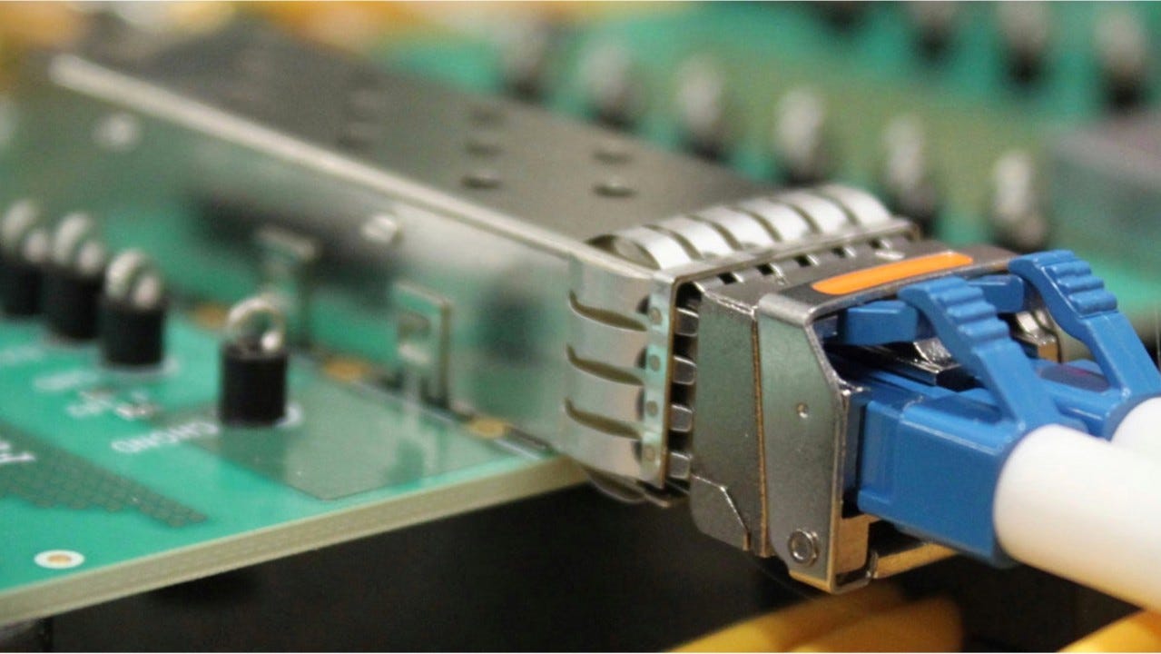
An MPO cable is a “ribbon” cable, where multiple fibres are laid flat and terminated in a single connector called a ferrule.
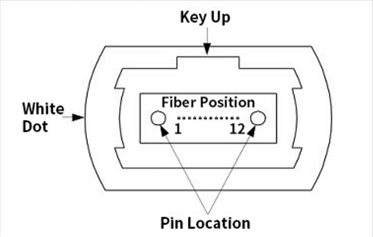
In MPO-12 cables, there are 12 fibres in a single row. The plastic connector housing has an alignment “key” centred on the top (see images below). On an MPO-16 cable, to prevent you from plugging this into a 12-fibre port (or vice-versa), the alignment key is offset to one side.
Channel Mapping
Transceivers are designed for a specific number of “lanes,” and each lane needs two fibres: one for Transmit (Tx) and one for Receive (Rx).
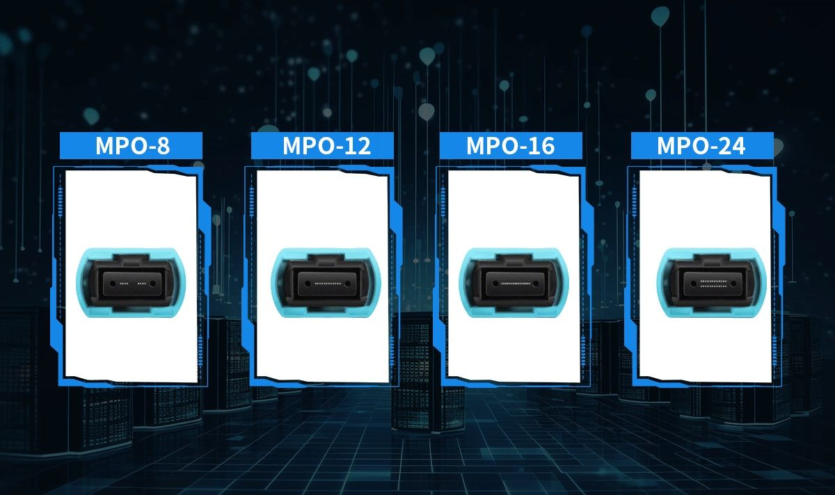
In 4-Lane optics (e.g., 100G-SR4, 40G-SR4), 4 fibres are needed for transmission and and 4 for receiving (4x Tx, 4x Rx), requiring 8 fibres (1-4 and 9-12) in total. The 4 fibres in the middle (5 - 8) are unused and “dark”.
In 8-Lane optics (e.g., 400G-SR8) however, 8 lanes (8x Tx, 8x Rx), requiring all 16 fibres in an MPO-16 cable.
How Splitter/Breakout Cables Work
Splitter cables adapt these high-density ports to connect to multiple lower-speed devices.
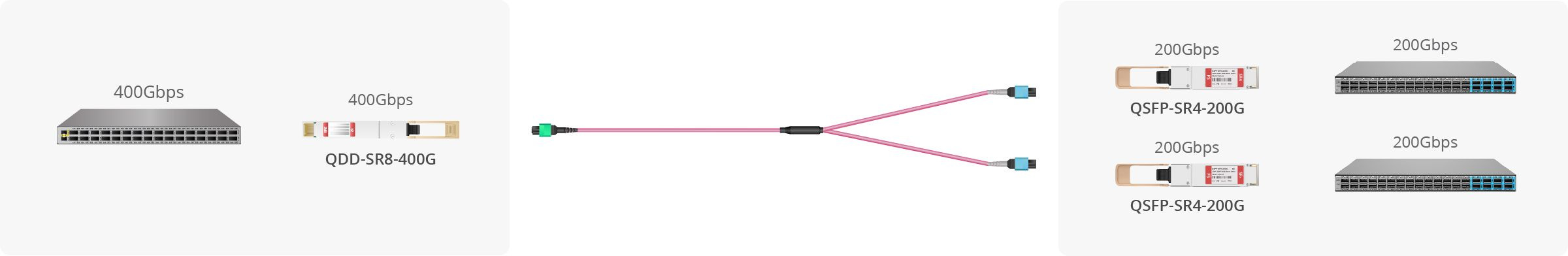
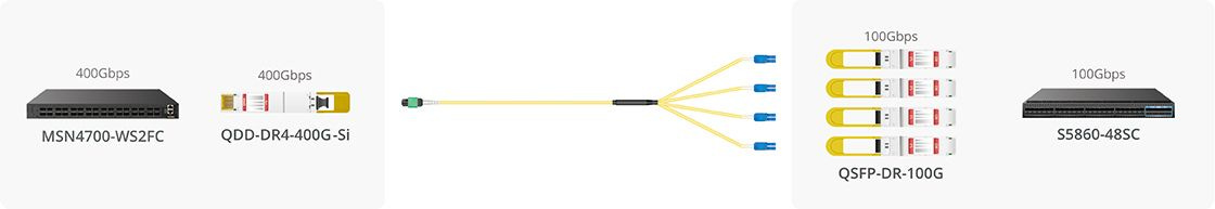
In the case of splitting from 400G 4-lane to 4x 100G single-lanes, a 400G-DR4 port (MPO-12) can be split using an MPO-12 to 4x Duplex LC (2 fibres each) breakout cable. For a 400G 8-lane to 2x 200G 4-lanes, a 400G-SR8 port (MPO-16) can be split using an MPO-16 to 2x MPO-12 (or maybe MPO-8?) breakout cable, which plug into 2 x 200G-SR4 transceivers.
The Case for Simpler Designs
Breakout cables are powerful but add complexity.
Inventory: You now have to manage inventory for MPO-MPO trunk cables, MPO-16 to 2xMPO-8 harnesses, MPO-12 to 4xLC fan-outs, etc. This is more complex than just stocking standard patch cords.
Lead Times: These multi-leg, complex harness cables are often custom-built and can have longer lead times.
Cost: The harnesses themselves can be more expensive upfront.
A simpler (though less dense) design using point-to-point cables can be easier to manage, source, and deploy.
In summary
Always verify with your transceiver datasheet before ordering cables. The 400G-SR8 standard explicitly requires 2x MPO-12 connectors for 200G-SR4 breakout—not MPO-8. Mismatched connectors and fibre counts are among the most common ordering mistakes in datacenter builds.
Image sources:
Comments:
Great post, Hitesh! One thing worth adding as speeds move to 800G and 1.6T:
Many modules marketed as SR8/DR8 are actually 2×SR4 or 2×DR4 designs and use dual MPO-12, not MPO-16.
Functionally fine, but important for planning — you’re really working with two separate 4-lane engines, which affects cabling, polarity and breakout expectations.
A small naming detail that can prevent big deployment surprises.
Follow up links:
FS.com Blog about breakout cables: https://www.fs.com/blog/what-is-the-breakout-connectivity-of-transceivers-and-cables-and-how-to-use-them-27754.html
A nice little page from HPE Aruba Networking on compatibility for optics when splitting: https://arubanetworking.hpe.com/techdocs/Switches/xcvrs/xcvr_guide/Content/Chp_overview/comp-split-opt-tran.htm
LINK-PP INT’L TECHNOLOGY CO.,LIMITED .‘s article on MPO cables: https://resources.l-p.com/knowledge-center/mpo-connectors-differences-8-12-16-24-fiber-comparison